Vesper Marine (now part of Garmin) WatchMate Vision XB-9000, serial number JZ70527, version 3.04.17316. Purchased 11/2022. I bought a refurbished unit with no warranty. The unit is 6⅞" wide x 5⅛" high x 2⅜" deep. It is a class B transponder. The AIS sends position reports every 30 seconds while the boat speed is faster than 2 knots; otherwise, it reports every 3 minutes. Other information like the vessel's name, size, and type, broadcasts every 6 minutes.
The antenna is at the top of the mizzen mast. It's a GAM Electronics SS-2 AIS tuned to AIS channel 162 MHz, 3dB gain. The antenna is about 2' above the masthead to clear the radar reflector.
The cable is Ancor RG-8X. I replaced the cable in 09/2024. The old cable's core was waterlogged. It tested good with an SWR meter, but the SWR reading also looked good if I disconnected it from the cable going up the mast.
All PL-259 connectors are crimp Amphenol 18115 with the center conductor soldered. I filled the PL-259 with silicone-based dielectric grease (Permatex 22058) to minimize water intrusion. I wrapped the outside of the connections with Skywalker cable sealant tape (SKY2627).
The cable from the AIS to the mizzen mast base is around 23'. In the mizzen mast, the cable length is around 26'.
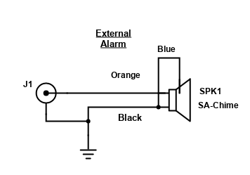
The AIS uses an external alarm that generates a "Ding-Dong" sound whenever a ship is within the alarm zone. The alarm signal can source 150 mA @ 12V:
Here's a link to my former Nasa Marine Radar AIS.
Cetrek (out of business)
Pilot Control - Model 730, serial number 012256/065
Pilot Computer - Model 930609. Jumper J3 is set to PWM, not spool valve.
Compass - 930 580
Hydraulic drive -
- Teleflex SeaStar, Model BA150-7TM, Part # HC5318, F971006
- Seal kit: HS5182
- Filler tube: HA5438
Hydraulic Pump
- Motor had a label on it that had the following information: MQ347 807628 PF26119Q 12VDC 14/08/96
- My search turned up the AccuLift MQ347 hatch lifter that has an electric motor that looks like this one.
- Possible motor manufacturers were Fasco and Owasso, but I couldn't confirm.
Valve from Vickers (Eaton)
- coil number 02-160678 12V.
- Proportional pressure reducing-relieving valve EPRV2-8 sliding spool.
- No arc suppression diode. If wanted, change part number to 02-178802 or add 800 Vr diode
- 1.32 amps when energized (16 watts).
Cetrek schematics were not available from the factory!
The cable from the 930609 Computer to the 730 Pilot Controller:
| 730 Pin Number | Wire Color | 930609 Pin Number |
|---|---|---|
| 1 | Red | 3 |
| 2 | Black | 6 |
| 3 | Brown | 1 |
| 4 | Yellow | 4 |
| 5 | Orange | 5 |
| 6 | Purple | 2 |
| 7 | Shield | — |
* The 730 pins are numbered with the notch at top. Pin 1 is the first pin to the right of the notch, looking at the end of the connector. The pin numbers go around counter-clockwise. Pin 7 is in the center.
Autopilot settings (2024)
| Info | Info+Mode | |||
|---|---|---|---|---|
| Setting | Value | Setting | Value | |
| LIGHT | LO | TYPE | SAILBOAT | |
| RUDDER | 10 | |||
| RESP | A | |||
| CR | 11 | |||
| TRIM | 4 | |||
| RUD | 00> | |||
| MOTSP | 100 | |||
| MOTRMP | 2 | |||
| NO | TRSPD | |||
| RDBND | 4 | |||
| RUDLIM | 5 | |||
| DGELIM | 6 | |||
| NOAMP | FB | |||
| TACKA | 100 | |||
| PSTEER | 5 | |||
| AUTO | CD | |||
Serial No. B10675353
Purchased 9/28/05
I purchased the original one in 1999. It failed after the knockdown in 2005. The seawater corroded the circuitry inside the cover and the unit was not repairable.
40 amps
Datamarine S-200DL (manual, schematics), S/N 025397. March, 2001 — I changed the alarm circuit to boost the voltage for the alarm from 8V to 12V. I got the schematics and they didn't agree with the parts and circuits on the PCB. I added a small perf board with a two-transistor alarm amplifier. The depth sounder now has a mechanical buzzer alarm (Star Micronics SMB-12) and a 100 dB piezo siren alarm (Amazon, no part number).
The O-rings for the transducer and the dummy plug are size Dash-127 (ID 1-7/16, OD 1-5/8, Thickness 3/32).
The replacement alarm switch is an NKK M2024S3A1W06 or C&K 7211MYZQE (or BE) (DP3T, short toggle, bushing mount, solder lugs). The black rubber cap is a C&K 759D02000 or an NKK AT428H.
The custom LCD is no longer available. DMI will replace the LCD with a new LCD module for $250 (2021).
Purchased 4/2002. Serial No. 3462-5752. Software version 01. The NMEA output failed in 5/06 while connecting AIS and VHF. The unit still worked, but no networking capability. Replaced the unit with a new one.
Purchased 5/2006. Serial No. 3470-4889. Software version 03.
Uses antenna GPA017 (GPA-017), serial no. 228334. 10m cable. Current at 12V: 1.7 mA with power "off", 169 mA with backlight of 1, 171 mA with a backlight of 4, 182 mA with a backlight of 6, and 195 mA with backlight at 8.
According to Furuno tech support, the antenna can be shortened (the manual says not to cut). The issue is that the connection has to be a good one. Also, the GPS antenna has to be at least one foot away from the SSB antenna.
Purchased in 2012 as a backup to the Furuno.
At nav station, a 300W pure sine wave inverter. Voltworks VK300S. This cuts off at an input voltage of 9.5V and emits an alarm for the low-voltage condition. It will not start running again until the voltage is restored and the unit's power cycled.
Below electrical panel, a 300W modified sine wave inverter. Whistler PP300AC.
In stereo cabinet, a 180W pure sine wave inverter. Wagan Tech Elite 180W 2200.
Datamarine S-100KL (manual, schematics), log option A-180. Moved the transducer 18" behind depth sounder and 5" starboard of stem so that it reads on all points of sail. The transducer is the SX-120.
The S-100KL outputs a 12V pulse every 0.1 miles. I connected this up to a mechanical odometer that I stripped from another device. This device now records nautical miles. I adjusted the wheels in the new log to approximate the number of miles that we've traveled with Willow.
The LCD display is replaceable. The new Datamarine folks sell the display for $50 or you can buy it from Mouser (www.mouser.com) for $4.20 (2007). The LCD display is made by Lumex and is part number LCD-S401C52TF. The Mouser part number is 696-LCD-S401C52TF. The display is easy to change—remove the circuit board, remove the old display from its socket by prying it gently out, and then put the new display in the socket. Make sure that you orient the display the correct way (look carefully at the display to see the orientation).
To remove the circuitry, remove the stainless clip (~4" diameter) inside the circumference at the back of the unit. Remove the locking nut on the display front. Pull the circuitry out from the back of the mounting case. If you forget to remove the switch locking nut, the switch may break. A replacement switch is C&K 7213MYCLE. The ..LE isn't very important. Also, NKK M2027SS1W01 (longer handle).
I changed the calibration pot (2024) with a 10-turn 10K pot with a locking handle. I also added a 33K resistor on the white wire leading to the pot. This arrangement gives me a 0.5kn adjustment range with the pot, centered around my boat's calibration. The lower the resistance the lower the boat's speed.
April 2003 — Link 2000-R serial number 6846, D/C 1202.
Software version H4.07
4 fuses AGC2 250V. These are used for the battery voltage sensing, power to the monitor, and charging monitoring.
Used to be made by Cruising Equipment and sold by Heart Interface. Both companies were bought by Xantrex Technology.
*** If BAT1 is dead, the Link 2000-R/Ideal Regulator won't work. To fix it, jumper BAT1 to BAT2 at the fuse block (port side engine compartment), start engine, run for 5 minutes, turn off engine, disconnect jumper, restart engine.
The unit emits a lot of EMI noise that affects the SSB reception. I traced it down to a number of issues:
Part No. 84-2006-03, $350!
** The high voltage protection in the Ideal Regulator will fail in a shorted condition if there is a high voltage event, for example, disconnecting the alternator while running. The part is D13, a transient voltage suppressor 1N6280A or 1.5KE24A. This is soldered into the Ideal Regulator board.
A lot of the parts are obsolete. Substitutions:
| Link 2000-R Part | Substitute Part |
|---|---|
| MPQ2907 | NTE2322 |
| TPQ222A | NTE2321 |
| MSP8098 | NTE123AP |
| MPQ6600A1 | None! |
| 1N6280A | 1.5KE24A |
| IRF540N MOSFET | Still good! |
| Setting | BATT1 | BATT2 |
|---|---|---|
| Charged V | 13.2 | 13.2 |
| Charged % | 2 | 2 |
| Batt Cap | 440 | 80 |
| Data |
|---|
| E91 |
| +82 |
| -300.3 |
| 22.5 |
| Function | Data |
|---|---|
| 01 | 1 |
| 02 | 0 |
| 03 | 70 |
| 04 | OFF |
| 05 | OFF |
| 06 | A087 |
| 07 | 0.5 |
| 08 | 1.24 |
| Function | Data | Function |
|---|---|---|
| 09 | OFF | |
| 10 | 110 | Alternator current limit |
| 11 | OFF | Batt #2 used for control |
| 12 | 130 | |
| 13 | 100 | |
| 14 | OFF | |
| 15 | ON |
| Barrier Strip |
20-Pin Header Right Pin Number |
20-Pin Header Wrong Pin Number (Board Labels) |
Function |
|---|---|---|---|
| 1 | 13 | 4 | AGND |
| 2 | — | — | COND |
| 3 | 9 | 6 | Light |
| 4 | 19 | 1 | 12/24V |
| 5 | 17 | 2 | BATT1 Voltage |
| 6 | 15 | 3 | BATT2 Voltage |
| 7 | 7 | 7 | B1SHG |
| 8 | 5 | 8 | B1SHB |
| 9 | 3 | 9 | B2SHG |
| 10 | 1 | 10 | B2SHB |
Raytheon RL9 (800-539-5539 NH)
RL9 Mariner Pathfinder Type No. M92557, Display Unit Type No. M92558, s/n LN25798.
Software version 2.3S. Software upgraded for free 12/98. Radar checked at factory July, 1999 and all ok.
Failed 9/05. IC5 (Toshiba TLP121 optoisolator) failed that's used for the CPU to read the standby/transmit key press. I replaced it with an NEC PS2701-1 and it works.
I added a very loud alarm to the radar with a switch so that with the radar in guard mode, the alarm will get everyone's attention.
Icom M710RT with AT130 antenna tuner, installed 4/2000. I rebuilt the power able inputs to the remote unit (under the nav station) in 2024—the power connector had corroded.
Backstay insulators — Top insulator (Sta-Lok 043-08) is 3' down from the masthead. The starboard backstay leg has an insulator (Sta-Lok 206-06 body, 134-06 fork, 20907-06 adapter screw) at the joining plate. The port backstay is connected at the chainplate to the antenna tuner. There is a 6' Teflon rod covering the lower port backstay wire — 5/16" ID, 7/16" OD. UV resistant based on my three-year simulated UV testing. Around the turnbuckle boot is a 1.5" Davis turnbuckle boot.
In series with the antenna, I have a Daiwa CN-101L SWR and power meter. It failed (no reflection indicated—2024). I soldered the wire-wrap connections and it started working. The CN-101L is no longer available. If I need to replace it, the replacement is the Daiwa CN-501H.
| Noise Source | Conducted | Radiated | Resolution |
|---|---|---|---|
| Water pumps | Yes | Yes | 0.01µF capacitors on motor leads fixed radiated noise |
| Refrigeration | Yes | Yes | Power line filter (20 amp) on SSB power leads stopped conducted noise |
| Voltage regulator | No | Yes | Changed 8-conductor cable from phone cable to cat 5 cable, improved grounds on the metal box |
| Alternator | Yes | Yes | Improved ground to engine block, added in-line alternator filter |
| Inverter | ?? | Yes | |
| Fans | ?? | ?? |
Radiated noise: If the noise disappears after disconnecting the antenna.
Conducted noise: If the noise does not disappear after disconnecting the
antenna. Also, with the volume at minimum, you can hear conducted noise as hum.
The following are acceptable lengths (in feet) for the antenna (including GTO-15) for the range of 1.6 MHz to 30 MHz:
23, 25, 26, 28, 29, 34, 37, 39, 40, 42, 43, 46, 47, 48, 51, 58, 59, 60, 63, 64, 69, 72, 77, 78, 79, 80, 81
I added copper screening to the hull inside the engine compartment. The copper screen was standard grade woven wore cloth, 16x16 mesh, 0.011" wire diameter. I estimate that I added about 22 ft.² of copper mesh.
Sony DSX-A415BT AM/FM/Bluetooth/iPod plug-in, S/N 3295273, new 5/2025. Firmware M20/S35. 55W x 4. Must make sure that it goes completely off when the OFF button's pressed or else it draws 0.5A. To do this, make sure that AUTO OFF is set to OFF and hold down the OFF button for about 3 seconds.
The built-in Bluetooth doesn't work throughout the boat! I installed a better Bluetooth transceiver (Esinkin W29-us) that uses the AUX input on the radio.
With low volume, the unit takes about 500mA. Pressing OFF, the current drops to 150mA for 13 seconds and then goes to <10mA. Most of the current goes through the yellow wire. The red wire is more of a signal wire (ACC connection).
I built a backup filtered supply thinking that the yellow wire just needed enough power to maintain the radio settings if the radio temporarily lost power. It was an inductor feeding a 22v 1.5F super-cap (4 5.5V 1.5F cap in series). It doesn't work well.
Cockpit speakers—Proficient Audio System AW400WHT.
L-Pad—Pro-Tech 260-264
Lots of digital thermometers around the boat (e.g., water temperature, icebox temperatures, etc.). Using an old Radio Shack model 63-1009 thermometer for each of these readings. It requires one AAA battery. The thermistor lead is 50KΩ @ 25°C (type J curve, -4.5%/°C).
In 2024, I bought a used Simrad TP10 Tillerpilot (s/n QD10192). I made a system to connect it to the Hydrovane so that I have a completely separate steering system in case the main autopilot failed of something jammed the rudder. The tillerpilot mounts to the starboard pushpit. All the tillerpilot items are in its zippered black bag. To deploy the tillerpilot:
Navman 7200US, S/N 4-0-V-12-0077, new 10/05. Replaced the microphone cable in 2022, since the old one's rubber disintegrated. The replacement was an Opek MC8-10 (7 conductors + shield, coiled cord). I spliced it to the old connectors and strain reliefs.
Metz 206 Manta VHF antenna (3dB gain, 34" long), 1¼" O-ring underneath, 1/8" thick.
RG8X cable
Call sign WCZ6619, MMSI 366777160.
I added (2024) an external waterproof VHF speaker. It's an MB-21 from Poly-Planar.
Icom IC-M25, new 2022, s/n 11007642. Replaced the Standard Horizon HX460S, from 2001 (volume decreased over time).
Icom IC-M25, new 2023, s/n 41002043 . Replaced the West Marine VHF100 from 2004, s/n 3G 00052 BG.
The stereo radio share the antenna on the main mast with the VHF. The splitter is a Shakespeare 4357-S. The unit is under the cabin sole in the same space as the knotmeter transducer.
It failed in 2021. The problem was a poor solder joint at the inductor connection to the FM output center pin. Here is the schematic I created.
The cable to the AM/FM radio from the splitter is RG-62/U with Motorola plugs on each end.
Heart Interface incharge 3-stage alternator regulator. Model 84-2006-00/N 124595. This regulator uses the same alternator cable as the Ideal Regulator with the Link 2000-R. I have plugged this in and tested it. It works, plus it has very low noise on the SSB.
Standard Horizon model WS45, S/N 13U600041. Purchased 3/02. Current usage is around 70 mA. With the backlighting on, the current jumps to 100 mA. Looks like this was made by Navman and remarketed by Standard Horizon.
Tri-cup assembly: XUNVM0073
Masthead cable (Navman): AA002615
The wind speed transducer puts out 2 pulses per revolution of the cup assembly (calibration chart). The wind direction is a quadrature output, one cycle per revolution. A common failure (happened to two of my instruments) is that the clear acrylic front of the meter separates from the black housing, so that nothing holds the meter in place.